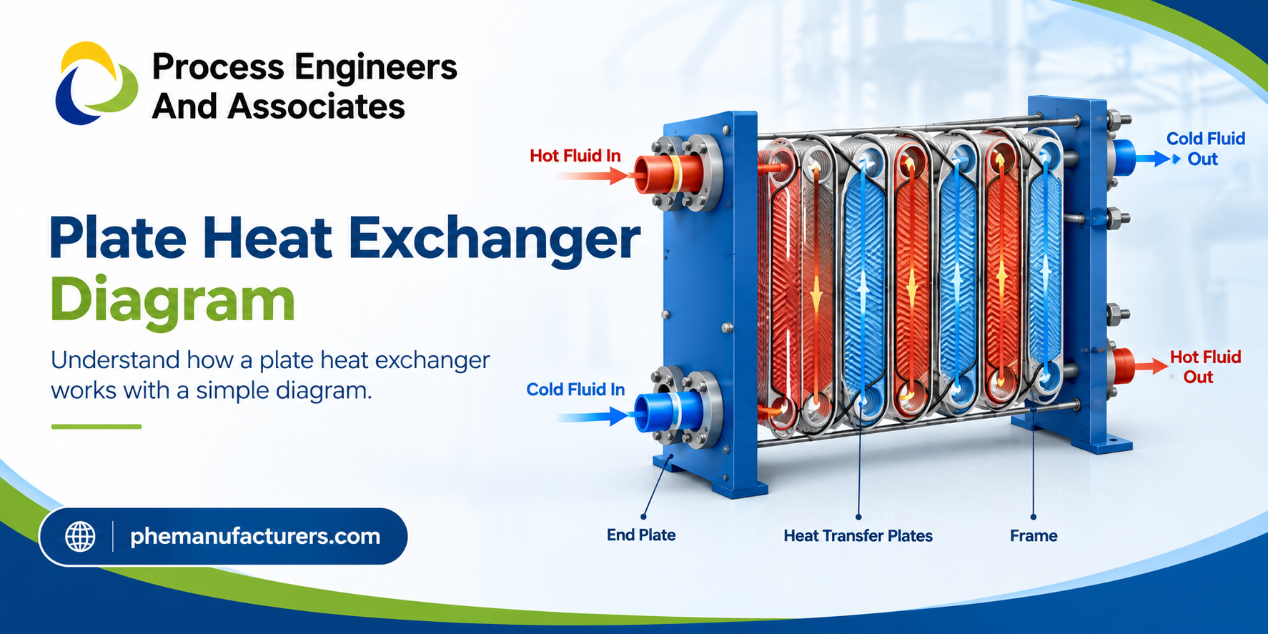
A plate heat exchanger diagram helps explain how two fluids transfer heat without directly mixing. It illustrates the arrangement of thin metal plates, fluid inlet and outlet ports, flow channels, gaskets, and the frame that holds the assembly together. Understanding this diagram makes it easier to identify components, follow fluid movement, and select the right heat exchanger for industrial applications.
Plate heat exchangers are widely used in industries where efficient heating and cooling are essential, including food processing, pharmaceuticals, HVAC, chemical processing, and power generation. For engineers, plant operators, and maintenance teams, knowing how to read the diagram can support better equipment selection, troubleshooting, and maintenance decisions.
Quick Answer: What Does a Plate Heat Exchanger Diagram Show?
A Plate Heat Exchanger Diagram shows how multiple thin, corrugated metal plates create alternating channels for hot and cold fluids. Heat passes through the plates from the hotter fluid to the colder fluid, while the two fluids remain separated. The main components include heat transfer plates, gaskets, inlet and outlet ports, a fixed frame plate, a movable pressure plate, and tightening bolts.
The diagram also illustrates the flow arrangement, which is commonly counter-current to improve thermal performance.
1. What Is a Plate Heat Exchanger?
A plate heat exchanger (PHE) is a thermal device that transfers heat between two fluids through a series of thin metal plates. Instead of using a single thick separating surface, it uses multiple plates to provide a large heat transfer area within a compact space.
The plates are usually manufactured from materials such as stainless steel or titanium, depending on the fluids, operating conditions, and corrosion requirements. Corrugated plate patterns promote turbulence and improve heat transfer, although they also create pressure drop that must be considered during design.
A plate heat exchanger diagram provides a visual overview of this arrangement and helps explain why plate heat exchangers can deliver efficient heat transfer in a relatively small footprint.
2. Main Components of a Plate Heat Exchanger Diagram
Understanding the individual components is the first step in interpreting the diagram correctly.
Heat Transfer Plates
The plates are the core working elements of the exchanger. Their thin construction and corrugated surfaces create channels for the process fluids while allowing heat to pass through the metal.
Common plate materials include:
- Stainless steel: Suitable for many water-based and general industrial applications.
- Titanium: Often selected for seawater and certain corrosive environments.
- Special alloys: Used when chemical compatibility or operating conditions require additional resistance.
Gaskets
Gaskets sit in designated grooves around the plates in gasketed plate heat exchangers. They direct each fluid into its intended channel and prevent external leakage and cross-contamination.
Gasket material must be compatible with the fluid, cleaning chemicals, temperature, and pressure.
Inlet and Outlet Ports
The ports allow hot and cold fluids to enter and leave the exchanger. Depending on the design, four main connections are commonly shown in a diagram: hot-fluid inlet, hot-fluid outlet, cold-fluid inlet, and cold-fluid outlet.
Correctly identifying these connections helps operators trace each fluid’s path through the equipment.
Frame Plate and Pressure Plate
The fixed frame plate supports the assembly, while the movable pressure plate allows the plate pack to be compressed or opened for inspection and cleaning.
Tightening Bolts
Tightening bolts hold the plate pack under the manufacturer’s specified compression. Correct tightening is important because insufficient or excessive compression can lead to leakage, deformation, or sealing problems.
Carrying and Guiding Bars
These bars support the plates and help keep them aligned during assembly, operation, and maintenance.
3. How Does a Plate Heat Exchanger Work?
The working principle is based on indirect heat transfer through a thin metal surface.
Step 1: Hot and Cold Fluids Enter
The hot fluid enters through its designated inlet, while the colder fluid enters through a separate connection. The two fluids follow different channels within the plate pack.
Step 2: Fluids Flow Through Alternating Channels
Gaskets and plate-port arrangements direct the fluids through alternating passages. In a typical arrangement, one channel carries the hot fluid and the adjacent channel carries the cold fluid.
Step 3: Heat Transfers Through the Plates
Thermal energy moves from the hotter fluid, through its boundary layer and the metal plate, into the colder fluid. The fluids remain physically separated when the exchanger is operating correctly.
Step 4: Corrugated Plates Improve Heat Transfer
The corrugations promote fluid mixing near the plate surface and increase the effective heat transfer area. This can improve thermal performance but may also increase pressure drop.
Step 5: Fluids Exit at Different Temperatures
The hot fluid leaves at a lower temperature, while the cold fluid leaves at a higher temperature. The final outlet temperatures depend on flow rates, inlet temperatures, heat transfer area, fluid properties, and exchanger design.
4. Understanding Fluid Flow in a Plate Heat Exchanger Diagram
Fluid flow is one of the most important details to examine in a diagram.
Counter-Current Flow
In counter-current flow, the hot and cold fluids move in opposite directions. This arrangement often provides a higher average temperature difference across the heat transfer surface, improving thermal effectiveness.
Parallel Flow
In parallel flow, both fluids enter from the same end and move in the same direction. The temperature difference between the fluids generally decreases along the flow path.
The actual flow arrangement depends on the exchanger’s port configuration and plate-pack design. Always refer to the manufacturer’s drawing before identifying connection locations or changing piping.
5. Types of Plate Heat Exchangers
Different plate heat exchanger designs serve different operating requirements.
| Type | Key Features | Common Applications |
| Gasketed plate heat exchanger | Plates can be opened for inspection, cleaning, and reconfiguration | HVAC, food processing, industrial utilities |
| Brazed plate heat exchanger | Compact construction with plates permanently joined by brazing | Refrigeration, heat pumps, compact heating systems |
| Welded plate heat exchanger | Welded construction for selected demanding process conditions | Chemical and industrial process systems |
| Semi-welded plate heat exchanger | Selected channels are welded, with gaskets used elsewhere | Certain refrigerant and chemical applications |
The right type depends on operating pressure and temperature, fluid compatibility, cleanliness, maintenance access, and the consequences of leakage.
6. Industrial Applications of Plate Heat Exchangers
Plate heat exchangers support energy-efficient heating and cooling across a wide range of industries.
- Food and beverage: Heating and cooling milk, beverages, and other process liquids.
- Pharmaceuticals: Controlling process temperatures where hygiene and contamination prevention are critical.
- HVAC systems: Transferring heat between building circuits, district heating networks, and chilled-water systems.
- Chemical processing: Heating or cooling compatible process fluids under defined operating conditions.
- Power generation: Supporting heat recovery and auxiliary cooling systems.
- Marine applications: Cooling selected systems using seawater-compatible materials where required.
For example, a food-processing facility may use a plate heat exchanger to transfer heat from hot process water to a colder water stream. A correctly sized unit can recover useful thermal energy, reducing the amount of energy needed to heat incoming water.
7. How to Read a Plate Heat Exchanger Diagram Correctly
Use the following practical checklist when reviewing a diagram:
- Identify all four connections. Confirm the hot and cold fluid inlets and outlets.
- Trace each fluid separately. Follow the port and channel arrangement without assuming that every plate has the same flow direction.
- Check the flow configuration. Determine whether the arrangement is counter-current, parallel, or another manufacturer-specific configuration.
- Identify plate and gasket details. Confirm the plate material and gasket compatibility for the intended service.
- Review design limits. Check the specified operating temperature, pressure, flow rate, and allowable pressure drop.
- Consult the manufacturer’s drawing. Use the correct model-specific drawing for installation, maintenance, and troubleshooting.
A generic diagram is useful for understanding the principle, but it should not replace an approved equipment drawing or installation manual.
8. Common Plate Heat Exchanger Problems and Maintenance Tips
Understanding the diagram also helps maintenance teams recognize possible problems.
Reduced heat transfer: Fouling, scaling, inadequate flow, or incorrect operating conditions may reduce thermal performance.
High pressure drop: Deposits, blocked channels, excessive flow, or unsuitable operating conditions can increase pressure drop.
External leakage: Damaged gaskets, incorrect plate alignment, or improper tightening may contribute to leaks.
Cross-contamination: A damaged plate can allow fluids to mix. If cross-contamination is suspected, follow the plant’s isolation and inspection procedures immediately.
To maintain performance:
- Monitor inlet and outlet temperatures and pressure drop.
- Follow the manufacturer’s cleaning recommendations.
- Select cleaning chemicals compatible with the plate and gasket materials.
- Inspect gaskets and plates during scheduled maintenance.
- Avoid tightening the plate pack beyond the specified dimensions.
Preventive maintenance helps preserve heat transfer performance, protect process quality, and reduce unexpected downtime.
Frequently Asked Questions
1. What is a plate heat exchanger diagram?
A plate heat exchanger diagram is a technical illustration showing the plates, gaskets, frame, ports, and fluid channels used to transfer heat between two separate fluids.
2. What are the main parts of a plate heat exchanger?
The main parts typically include heat transfer plates, gaskets, inlet and outlet ports, a fixed frame plate, a movable pressure plate, tightening bolts, and carrying or guiding bars. The exact configuration varies by model.
3. How does a plate heat exchanger transfer heat?
Hot and cold fluids flow through separate channels divided by thin metal plates. Heat passes through the plates from the hotter fluid to the colder fluid without direct mixing during normal operation.
4. Why is counter-current flow used in plate heat exchangers?
Counter-current flow often maintains a more favorable temperature difference across the exchanger, helping improve heat transfer effectiveness compared with parallel flow under comparable conditions.
5. How do I choose the right plate heat exchanger?
Consider the required heat duty, inlet and outlet temperatures, flow rates, operating pressure, pressure drop, fluid properties, corrosion resistance, cleaning requirements, and available installation space. A qualified supplier or thermal design engineer can help verify the selection.
Conclusion
A plate heat exchanger diagram makes it easier to understand the equipment’s components, fluid flow paths, and heat transfer process. From plates and gaskets to inlet and outlet connections, every component contributes to reliable thermal performance.
Understanding the diagram can help engineers, plant operators, and maintenance teams make better decisions about equipment selection, troubleshooting, cleaning, and long-term operation. However, final equipment selection and installation should always be based on the actual process requirements and the manufacturer’s approved documentation.
Looking for a Reliable Plate Heat Exchanger Solution?
Process Engineers And Associates can be your starting point for discussing plate heat exchanger requirements for industrial heating and cooling applications.
Contact us today to discuss your process requirements, explore suitable heat exchanger options, and identify the technical information needed for an appropriate solution. Visit us to learn more about our offerings and how we can support your industrial heat transfer needs.